|
|
How to Display a Basic Event comming from Your Experimental Data ?
This project contains 3 functions + the main :
Build_Geometry() method will create the geom file associated to our detector.
In this example, we'll build a more realistic appartus.
Our experiment will be composed of 10 tracking planes.
The Build_1Event() method will fill the myEvents objects with all data related to 1 Event.
In our cases, random variables will be used inside this function to simulate a particle gun.
The myEvents will be created by the third function Build_Events(). This method will also call Build_1Event() N Times.
Where N is the number of events we want to store/display.
Finally the main() function will first call the GeometryBuilder, then initialise the MyEvents objects
After that, it will enter in the events loop. And call the Build_1_Events function at each loop.
Finally, we'll store events data in a .vis file which can be read by FROG.
1. The Includes
Includes are basically the same than in the previous tutorial. Except that FROG_Events.h and FROG_Element_Event_Track.h have been added. The first one, will do exactly same thing that FROG_Element_Geometry. It contains the Load/Save functions. The second one will store our event data. Which will be a track in this example.
#ifdef linux
   #include <GL/gl.h>
   #include <GL/glu.h>
   #include "../../Includes/GLUT/glut.h"
#else
   #define _CRT_SECURE_NO_DEPRECATE 1
   #include <windows.h>
   #include <gl/gl.h>
   #include <gl/glu.h>
   #include <gl/glut.h>
   #pragma comment (lib,"glaux.lib")
   #pragma comment (lib,"glu32.lib")
   #pragma comment (lib,"opengl32.lib")
   #pragma comment (lib,"glut.lib")
   #pragma comment (lib,"glut32.lib")
#endif

#include <stdio.h>
#include <iostream>
#include <math.h>

#include "../../Includes/FROG/FROG_DetId.h"
#include "../../Includes/FROG/FROG_Geometry.h"
#include "../../Includes/FROG/FROG_Events.h"

#include "../../Includes/FROG/FROG_Element_Tools.h"
#include "../../Includes/FROG/FROG_Element_Event_Track.h"
2. The Four Functions
Now we can define the three functions (in addition of the main) we will use :
void Build_Geometry();
void Build_Events();
void Build_1Event(FROG_Element_Event* event);
3. Build the Geometry
This I will note comment because it is the topic of the previous tutorial. We use exactly the same Idea. The Geometry is composed of 10 tracking layer. Orthogonal to the Z axis. Each layer are square plane with a dimention of 100 x 100 (cm). The layers are positioned on (0,0,50*i) where i = 0, 1, 2, ..., 10 (so actually we have 11 layers ;) )
We create also 2 others geometry objects : the particle gun (at 0,0,-300) and what I call a mirror wall (at 0,0,600). This object is just a cube. That will reflect our beam, exactly as a mirror does with the light. Add the end of the fucntion I save the geometry into the file "MyCustomTracker.geom".
void Build_Geometry()
{
  // This element is the root of the "file" tree.  (don't change this line)
  ROG_Element_Base* prim = new FROG_Element_Base(C_PRIMARY);

  // This element is the geometry branch of the tree.  (don't change this line)
  // When the element have been created, we have to attach it to the root (or more generally to the mother branch).
  FROG_Element_Base* mygeom = new FROG_Element_Base(C_GEOMETRY);
  prim->addDaughter(mygeom);

  // This a particular geometry branch : this allow us to group all the detectors attached to this branch.
  // Moreover, this group of detector as a detId, which allow us to easily "call" this group (e.g. for the display).
  // Warning : be sure that the detId is not already use by an other detecor.  (detId should be bigger than 1000000).
  // Warning : an empty group (containing 0 elements) can not be save.
  FROG_Element_Base_With_DetId* tracker = new FROG_Element_Base_With_DetId_And_Name(9000000,"Tracker");
  mygeom->addDaughter(tracker);

  // This variable will allow us to do not use twice the same detId.
  unsigned int DetIdCount = 1;

  // We'll fill the tracker group with 10 primitive objects.  A lots of primitive objects can be use in FROG.
  // You can find all the primitive header files in <FROGDIR>/soft/Includes/FROG/FROG_Element_Primitive_*.h
  // There is also some CMS oriented dataformat : <FROGDIR>/soft/Includes/FROG/FROG_Element_Geom_*.h
  // Do not hesitate to add your own primitive objects.  There are really easy to do (takes an existing primitive as example
  // and copy/paste to build your own).

  for(int i=0;i<=10;i++){
    FROG_Element_Primitive_Rectangle* layer = new FROG_Element_Primitive_Rectangle(400000000+DetIdCount,
      0  ,0  ,50*i,	//Position
      50 ,0  ,0   ,	//Width
      0  ,50 ,0   );	//Length
    tracker->addDaughter(layer);
    DetIdCount++;
  }

  // This group will contains all no realistic objects. For Instance, a cube will symbolised the Particle Gun.
  // And an other cube will symbolise the mirror wall.
  FROG_Element_Base_With_DetId* others = new FROG_Element_Base_With_DetId_And_Name(8000000,"Others");
  mygeom->addDaughter(others);

  FROG_Element_Primitive_Cube* End = new FROG_Element_Primitive_Cube(400000000+DetIdCount,
    0  ,0  ,600,    //Position
    50 ,0  ,0   ,   //Width
    0  ,50 ,0   ,	  //Length
    0  ,0  ,50  );  //Thickness
  others->addDaughter(End);   DetIdCount++;

  FROG_Element_Primitive_Cube* PG = new FROG_Element_Primitive_Cube(400000000+DetIdCount,
     0  ,0  ,-300,   //Position
     5  ,0  ,0   ,   //Width
     0  ,5  ,0   ,   //Length
     0  ,0  ,50  );  //Thickness
  others->addDaughter(PG);   DetIdCount++;

  // Now that the geometry tree is build.  We can create the geometry objects with this tree.  The geometry Object
  // will handle the writting/reading of geometry files.  It has also a very useful function to get a branch or a leaf of the tree
  // from his detId (Geometry::FindByDetId).
  FROG_Geometry* CustomGeom = new FROG_Geometry(prim);
  CustomGeom->Save("MyCustomTracker.geom");

  // Last but not least, the FROG_ELEMENT::PrintTree function will print on the screen the tree arborecence.
  // Check this print out to see if your groups are done as you want, and to see if no modules are missing.
  FROG_ELEMENT::PrintTree(prim);

  // If everything works fine, You just have to update the FROG's config.txt to load your geometry.
  // You can for instance replace
  // InputTrackerGeom = ../test/Tracker.geom;
  // by
  // InputTrackerGeom = <FROGDIR>/soft/Examples/02_Display_Basics_Events/MyCustomTracker.geom;

  return;
}
4. Build the Event Tree
Now, we can create the Event Tree. As it is done for the geometry, first we need a root of type FROG_Element_Base with a chunkId of type C_PRIMARY.
Then we can add event branch on this root. Each branch should be of type FROG_Element_Event. The constructor of this method can take the EventNumber and the RunNumber as parameter. Default values are 0. Then we shoudl fill the Event branch with the data of the particular event. This is the job of the Build_1Event function. This function take a pointer of the event branch in argument. These operation are repeated N(=10) times. In order to simulate/store 10 events. Of course you can increase this Number in order to display more events (there is no limitation on the number of events). Finally, When the tree is complete, we can create a FROG_Events object, which will allow us to save the tree on the disk. Thanks to the function save. Let's call the events file : "SimulatedEvents.vis"
void Build_Events()
{
  // This element is the root of the "file" tree.  (don't change this line)
  FROG_Element_Base* prim  = new FROG_Element_Base(C_PRIMARY);

  // Prepare to simulate 10 events.
  for(unsigned int i=0;i<10;i++){

    // Create a new event
    FROG_Element_Event* event =  new FROG_Element_Event(1,i);

    // Fill the event with monte carlo
    Build_1Event(event);

    // Store the event
    prim->addDaughter(event);
  }

  // Save the event tree on disk
  FROG_Events* events = new FROG_Events(prim);
  events->Save("SimulatedEvents.vis");

  //      print the tree of all elements
  //      FROG_ELEMENT::PrintTree(prim);
}
5. Build One Event
This is the most important function. (and basically the only one you have to change). In this particular example, we need to simulate the event and to store it at the same time. So first, I define a large number of variables that are used to define the particle gun direction and position, particle direction and Pt.
Then I create 2 FORG_Objects. The first one is a FROG_Element_Base_With_DetId it will contains all the reco tracks in the event. (we will have only one track... but we want to put this track in a "group" in order to give it a name). The "name" of this group is no more a DetId, but and EvtId which is actually the same that the DetId but for event.
The second object is the track itself. This object is of the type FROG_Element_Event_Track. There is a lot of predefine Event_Object that you can use to store and display your events. Some of them are listed bellow (and an other tutorial will explains you how to create your own Objects) :
- Frog_Element_Event_CaloHit
- Frog_Element_Event_Hit
- Frog_Element_Event_Segment
- Frog_Element_Event_Sim_Hit
- Frog_Element_Event_Sim_Track
- Frog_Element_Event_Sim_Vertex
- Frog_Element_Event_Track
The constructor of the FROG_Element_Event_Track takes the P, Pt and Chi2 as input. The first parameter should be 0 (this argument will be remove soon... it is there only for back-portability). This object will take the Hits on the tracker layer as daughters/leaves.
So we have to create the hits on all the layers... So the following is basically the particle propagation in the detector (this step can be done with Geant4). When the particle cross a layer, I just create a new hit. Which is define by the DetId of the layer that produce the Hit, a X,Y,Z position (in the global frame) and an energyLoss (always equal to 0 in this tutorial). Also, if the particle reach the "mirrow wall" I just flip the Z component of the particle momentum.
Finally, I just plug the track branch on the trackCollection branch. And the trackCollection branch on the Event branch.
void Build_1Event(FROG_Element_Event* event)
{
  // Define particle Gun direction and strength (8° in theta, 360° in phi and 10GeV)
  double phi   = (rand()%360)*0.01745;
  ouble theta = (rand()%8) *0.01745;
  ouble P	 = 10;

  // Define the particle gun position (starting point of particles)
  double pos_x = 0;
  double pos_y = 0;
  double pos_z = -300;

  // Define the particle cartesian direction
  double dir_x = P*cos(phi)*sin(theta);
  double dir_y = P*sin(phi)*sin(theta);
  double dir_z = P*cos(theta);

  // Create the track to be stored in the events.
  float Pt =  sqrt(dir_x*dir_x + dir_y*dir_y);

  FROG_Element_Base_With_DetId* trackCollection = new FROG_Element_Base_With_DetId_And_Name(EVTID_TRK,"Tracks");
  FROG_Element_Event_Track* track= new FROG_Element_Event_Track(0,P,Pt,0);

  // Begin the propagation loop
  double dt = 0.1;
  for(unsigned int i=0;i<10000;i++){
    pos_x += dir_x * dt;
    pos_y += dir_y * dt;
    pos_z += dir_z * dt;

    // There is no detector in the z<0 region, so continue the propagation until
    // the particle arrive in a detector region.
    if(pos_z<0     ) continue;

    // This means the particle is hitting the mirror wall.  So we inverse the particle Z direction
    if(pos_z>=600-25){
       dir_z = -1*dir_z;
    }

    // Check if we are crossing a tracker layer
    // If we are, create a hit with the detId of the crossed layer
    // and the position of the particle.  Charge can be used to set a dE/dx
    if(((int)pos_z)%50==0){
       if(fabs(pos_x)>50)continue;
       if(fabs(pos_y)>50)continue;
       FROG_Element_Event_Hit* hit = new FROG_Element_Event_Hit(400000001 + ((int)pos_z)/50, pos_x, pos_y, pos_z, -1);
       track->addDaughter(hit);
    }
  }

  // Store the built track in the events
  trackCollection->addDaughter(track);
  event->addDaughter(trackCollection);
}
6. Putting Everything Together into the main()
Finally, we only need to call Build_Geometry and Build_Events. That's all.
You can also to be sure that everything is correct read the Events file you saved.
If something is wrong, you will have some error messages at the reading. You can also display the Events tree (this can be a huge print out !!!).
int main()
{
  // Build and Save the geometry
  Build_Geometry();

  // Build and Save the event collection
  Build_Events();

  // The following lines are used to check if the output .vis file can be read correctly:
  std::cout << "--------- check output file ---------" << std::endl;
  FROG_Events* evt = new FROG_Events();
  evt->Load("SimulatedEvents.vis");
  FROG_ELEMENT::PrintTree(evt->prim);
}
7. The Frog config file
Now, as usual, we have to setup the FROG config file in order to display what we want.We can specify the geometry file, the events file.
But also the Geometry we want to display (9000000=Tracker & 8000000=MirrorWall+ParticleGun) and Event data we want to display (23100000) = RecoTracks.
Then we can set up views. It can be nice to have 3 views for this experiment : The standard 3D view, a longitudinal 2D view and a transversal 2D view (not so usefull!).
Finally we can set the style (color, thicknes, marker ans so on) of the recoTracks. The full config file can be found here.
//It is possible to load other config file from this one.

// input event file
InputVisFile = {Examples/02_Display_Basics_Events/SimulatedEvents.vis};

// input geometry file
InputGeom = {Examples/02_Display_Basics_Events/MyCustomTracker.geom};

GeomToDisplay  = {9000000, 8000000};
EventToDisplay = {23100000};          // All RecoTracks

ActiveViews = {View3D, View2DZ, View2DR};

View3D_Type           = 3D;
View3D_Viewport_X     = 0.0;
View3D_Viewport_Y     = 0.3;
View3D_Viewport_W     = 1.0;
View3D_Viewport_H     = 0.8;
View3D_Cam_Pos_Theta  = 0.3;
View3D_Cam_Pos_Phi    = 0;
View3D_Cam_Pos_R      = 500;
View3D_Animate_Rotate = false;
View3D_Animate_dphi   = 0.005;
View3D_Geom           = {9000000, 8000000};

View2DZ_Type          = 2D;
View2DZ_Viewport_X    = 0.4;
View2DZ_Viewport_Y    = 0.0;
View2DZ_Viewport_W    = 0.6;
View2DZ_Viewport_H    = 0.2;
View2DZ_Cam_Pos_Phi   = 0.01;
View2DZ_Cam_Pos_R     = 600;
View2DZ_Slice_Depth   = 800;
View2DZ_Geom          = {9000000, 8000000};

View2DR_Type          = 2D;
View2DR_Viewport_X    = 0.1;
View2DR_Viewport_Y    = 0.0;
View2DR_Viewport_W    = 0.2;
View2DR_Viewport_H    = 0.2;
View2DR_Cam_Pos_Phi   = 1.57;
View2DR_Cam_Pos_R     = 100;
View2DR_Slice_Depth   = 1000;
View2DR_Geom          = {9000000, 8000000};


// The Extension of File Containing ScreenShots
// PNG, PS, EPS, TEX, PDF, SVG and PGF(Experimental) Can be used
Screenshot_Format = png;


Id_23100000_Color          = { 1.0 , 0.0 , 0.0 , 1.0 };                 // ALL RecoTracks
Id_23100000_Thickness      = 4.0;                                       // ALL RecoTracks
Id_23100000_Marker         = 100;                                       // ALL RecoTracks
Id_23100000_MarkerSize     = 5;                                         // ALL RecoTracks


// WARNING : TABULATION CREATES BUGS & ERRORS
// SO PLEASE, USE WHITE SPACE INSTEAD OF TABULATION.
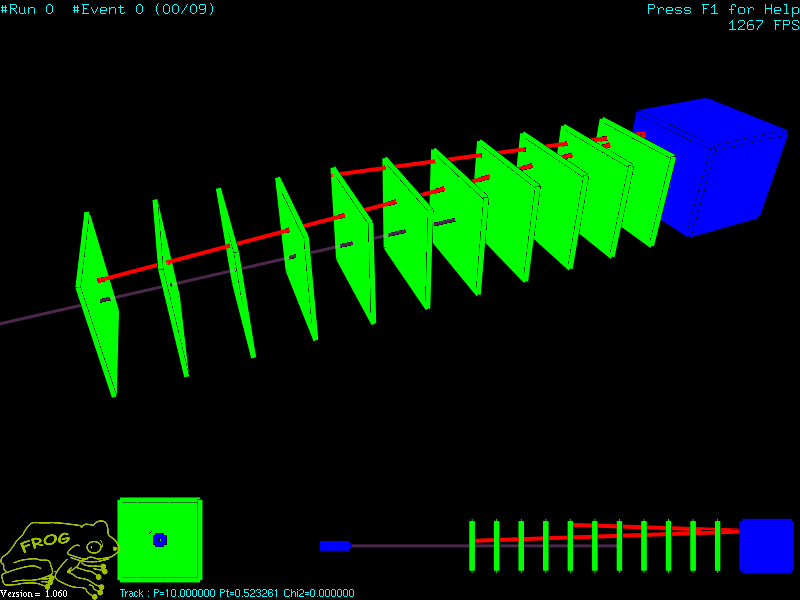
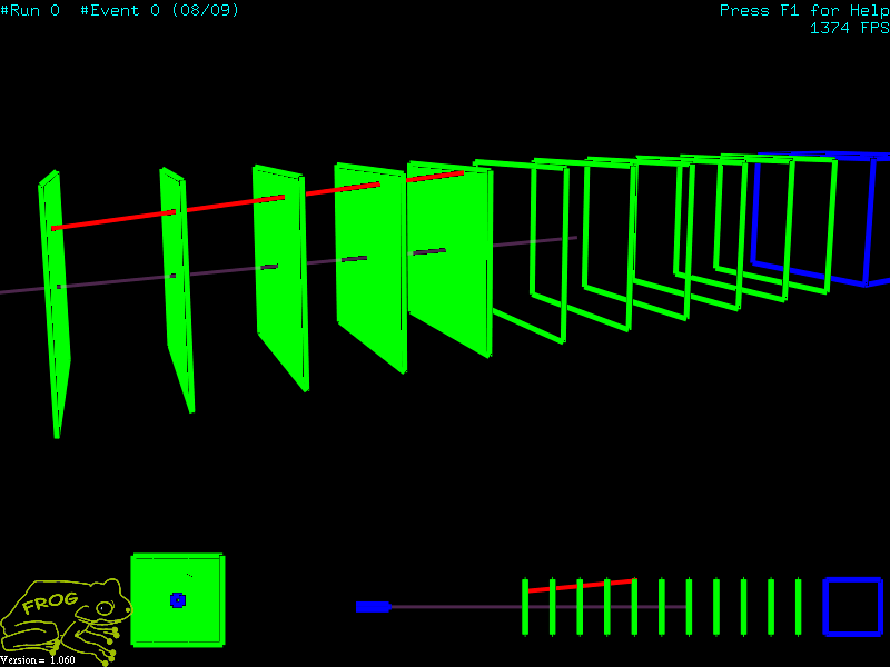
8. The Results
The full code, with the makefile and the visual c++ project can be found in "/Examples/02_Display_Basics_Events".
Have fun, and please send me a screenshot of your geometries and events data.
|